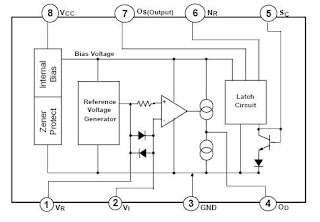
Saturday, December 12, 2009
Waveform Generator IC
MAX038
High-Frequency Waveform Generator
The MAX038 is a high-frequency, precision function
generator producing accurate, high-frequency triangle,
sawtooth, sine, square, and pulse waveforms with a
minimum of external components. The output frequency
can be controlled over a frequency range of 0.1Hz to
20MHz by an internal 2.5V bandgap voltage
reference and an external resistor and capacitor. The
duty cycle can be varied over a wide range by applying
a ±2.3V control signal, facilitating pulse-width modulation
and the generation of sawtooth waveforms.
Frequency modulation and frequency sweeping are
achieved in the same way. The duty cycle and frequency
controls are independent.
Feature♦ 0.1Hz to 20MHz Operating Frequency Range
♦ Triangle, Sawtooth, Sine, Square, and Pulse
Waveforms
♦ Independent Frequency and Duty-Cycle
Adjustments
♦ 350 to 1 Frequency Sweep Range
♦ 15% to 85% Variable Duty Cycle
♦ Low-Impedance Output Buffer: 0.1
♦ Low 200ppm/°C Temperature
datasheet
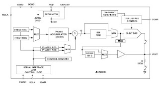
AD9833
Low Power 20 mW 2.3 V to 5.5 V
Programmable Waveform Generator
GENERAL DESCRIPTION
The AD9833 is a low power programmable waveform generator
capable of producing sine, triangular, and square wave outputs.
Waveform generation is required in various types of sensing,
actuation, and time domain reflectometry applications. The output
frequency and phase are software programmable, allowing easy
tuning. No external components are needed. The frequency registers
are 28 bits; with a 25 MHz clock rate, resolution of 0.1 Hz
can be achieved. Similarly, with a 1 MHz clock rate, the AD9833
can be tuned to 0.004 Hz resolution.
The AD9833 is written to via a 3-wire serial interface. This serial
interface operates at clock rates up to 40 MHz and is compatible
with DSP and microcontroller standards. The device operates
with a power supply from 2.3 V to 5.5 V.
The AD9833 has a power-down function (SLEEP). This allows
sections of the device that are not being used to be powered down,
thus minimizing the current consumption of the part, e.g., the DAC
can be powered down when a clock output is being generated.
The AD9833 is available in a 10-lead MSOP package.
FEATURESDigitally Programmable Frequency and Phase
20 mW Power Consumption at 3 V
0 MHz to 12.5 MHz Output Frequency Range
28-Bit Resolution (0.1 Hz @ 25 MHz Ref Clock)
Sinusoidal/Triangular/Square Wave Outputs
2.3 V to 5.5 V Power Supply
No External Components Required
3-Wire SPI® Interface
Extended Temperature Range: –40_C to +105_C
Power-Down Option
10-Lead MSOP Package
datasheet
CG-402R2
Sine wave output
Frequency can be set with two external resistors
Low distortion
Frequency ranges 20Hz to 1MHz
Technical specification
Output waveform Sine wave
Output voltage 2.5Vrms (variable)
Frequency setting method External resistor x2
Power supply voltage ±15V ±10%
Temperature humidity range Operation: -20 to 70°C, 10 to 95% RH
Storage -30 to +80°C, 10 to 80% RH
Technical data
Type Frequency Frequency stability External
CG-102R1 20Hz to 20kHz ±15ppm/°C 24-pin DIP
CG-402R1 20Hz to 20kHz ±50ppm/°C 12-pin SIP
CG-402R2 1kHz to 100kHz ±50ppm/°C 12-pin SIP
datasheet
Sunday, December 6, 2009
Melody IC
MELODY INTEGRATED CIRCUIT
DESCRIPTIONThe UTC UM66TXXL series are CMOS LSI designed for using
in door bell, telephone and toy application. It is an on-chip ROM
programmed for musical performance. Produced by CMOS
technology, the device results in very low power consumption.
Since the UTC UM66TXXL series include oscillation circuits a
compact melody module can be constructed with only a few
additional components.
FEATURES
*64-Note Rom memory
*1.5V ~ 4.5V power supply and low power consumption
*Dynamic speaker can be driven with external NPN
transistor
*OSC resistor hold mode
*Power on reset: melody begins from the first note
*Built in level hold mode
FUNCTIONAL DESCRIPTION
OSCILLATOR CIRCUITThe oscillator frequency is used as a time for tone and beat generators. Its accuracy affects the quality of the music.
TONE GENERATOR
Tone Frequencies are oscillator frequencies-M, where m is any even number from 64 to 256. Within a melody 14C scales can be selected including Pause code and End code. The tone generator is a programmed divider, The Range of Scales is from “C4” to “C6” and range of frequency varies from 258Hz to 23768Hz.
RHYTHM GENERATORThe rhythm generator is also programmed dividers. It contain 15 available rhythms as
follows:1/4,1/2,3/4,1,1-1/4,1-1/2,1-/3/4,2,2-1/4,2-1/2,2-/3/4,3,3-1/4,3-1/2,3-/3/4.Four rhythms can be selected from these.
MELODY ROM
The Mask Rom can memorize 64 notes with 6 bit.4 bits are used for controlling the scale code and 2 bits are used for controlling the rhythm code.
TEMPO GENERATOR
There are 15 available tempos in the UTC UM66T series. The 15 tempos are:128,137,148,160,175,192,213,
240 , 274, 320,480,640,960,1920 J/minute.
Datasheet pdfhttp://www.utc-ic.com/spec/UM66TXXL.pdf
Melody IC SVM7910
Product FeaturesDebuting in 1978, the SVM 7910 electronic sound-generating device was the world’s
first melody IC, taking advantage of CMOS IC technology derived from the
development of quartz watches. The first finished product equipped with this device
was the Seiko Electronic Melodia, a quartz alarm clock released by Seikosha* in July
1978. A revolutionary product, the Electronic Melodia could produce three types of
electronic sounds—a melody, chimes, and a buzzer—each selected by simply
pressing a button.
Later, in April 1983, came the advent of the SVM7960, part of the SVM79 melody IC
series. With a maximum performance capacity of four songs, and a wide operating
voltage range, from 1.5 to 5 volts, the emergence of this melody IC filled out the
SVM79 series lineup, and expanded the range of sounds that could be expressed.
Datasheet pdf
http://www.epson.co.jp/e/company/milestones/10_svm7910.pdf
FT66T32S Simple Melody Generator ICGeneral DescriptionThe FT66T series is a CMOS LSI designed melody generator IC for use in telephones and toys application. It has an on-chip ROM programmed for musical performance. Produced by CMOS technology, the device results in very low power consumption. And with built-in RC oscillator, a compact melody module can be constructed with only a few additional components.
Features
- One Short Mode, Song : Walts
- 64-note ROM memory
- Bulit-in RC oscillator
- 1.3V to 3.3V operating voltage and low power consumption
- Level-hold mode to play repeatedly
- Dynamic speaker can be driven with external NPN transistor.
- Packaged in inexpensive TO-92 package
Datasheet pdf
http://www.warf.com/electronic-products-1492.html
H66T19/32/68 Series
Description
The H66T19/32/68 series is a CMOS LSI designed for use in door bell,
telephone and toy applications. It is an on-chip ROM program-med for
music performance. Produced by COMS technology, the device results in
very low power consumption. Since the H66T19/32-/68 series includes
oscillation circuits, a compact melody module can be constructed with only
a few additional components.
Feature
64-Note ROM memory
1.5V to 3V power supply and low power consumption
Dynamic speaker can be driven with external NPN transistor
OSC resistor is built-in
Built-in level hold mode
Power on reset: melody begins from the first note
Datasheet pdf
http://kr.ic-on-line.cn/IOL/viewpdf/H66T19AA_76262.htm
7910 Series
Multi-Melody IC
DESCRIPTIONThe series 7910 is a CMOS IC which plays prearranged melodies and alarm sounds electronically. Built-in oscillation circuit generates acoustic pulses, then melodies and alarm sounds are formed with only a few external discrete parts including resistor, capacitor, speaker etc. Thus the 7910 can enjoy various applications such as replacement for conventional music box and alarm sound generator.
NOTE: These are ongoing user service products.
FEATURES
- Melody ............................ 2 or 1
- Musical interval .................. Temperament or pure temperament
- Sound ............................. 2 series, 2.5 octave
- Compound interval or accompaniment are possible.(One octave interval)
- Tempo ............................. 16 kinds(Prest to Largo). Two tempos in one piece.
- Note ............................. Basic note , and also possible for
- Rest .............................. According to note
- Repeat ........................... Continuous performance of pieces, and repeats(8 times at most)of a piece.
- Beginning ......................... Always starts at the beginning of piece.
- Alarm Chime ....................... Two (not always equipped)
- Input signal ...................... 1 start signal, 3 selective signals.
- Envelope .......................... External CR(2 series)
- Volume control .................... From external circuit(volume etc.)
- Oscillation ....................... C, R oscillator (C, R external connection)
- Voltage ............................1.5V
- Package .......................... DIP-16pin(plastic)
Datasheet pdfhttp://www.es.co.th/Schemetic/PDF/7910CR-EPSON.PDF
Sunday, November 15, 2009
EARTH LEAKAGE CURRENT DETECTOR ICs
EARTH LEAKAGE CURRENT DETECTOR
FUNCTION
The UTC M54123L circuit for the amplifying parts of earth leakage circuit breaker consists of differential amplifier, latch circuit and voltage regulator. It is connected to the secondary side of the zero current transformer (ZCT) which detects leakage current in the both input of the differential amplifier. Signals amplified by differential amplifier are integrated by an external capacitor, and connects to the input terminal of latch circuit with output suitable for the characteristics of high- speed earth leakage circuit breaker. Latch circuit keeps low in the output till the input voltage reaches the fixed level, and output becomes high when the leakage current more than fixed flows.
It drives a thyristor connected to the output terminal of latch circuit.
FEATURES*Suitable for JIS C 8371
*Good temperature characteristics of input sensitivity
current
*High input sensitivity (VT=6.1mV Typ.)
*Low external component count
*High noise and surge-proof
*Low power dissipation (Pd=5mW Typ.) and may be
used both as 100V and 200V.
*Wide temperature range (Ta=-20~+80°C)
Datasheethttp://www.unisonic.com.tw/datasheet/M54123L.pdf
KA2803B
Earth Leakage Detector
DescriptionThe KA2803B is designed for use in earth leakage circuit
interrupters, for stable operation of the AC line in breakers.
The input of the differential amplifier is connected to the
secondary coil of ZCT(Zero Current Transformer). The
amplified output of differential amplifier is integrated at
external capacitor to gain adequate time delay that is
specified in KSC4613. The level comparator generates high
level when earth leakage current is greater than the fixed
level.
Features
• Low Power Consumption PD =5mW, 100V/200V
• Built-in Voltage Regulator
• High Gain Differential Amplifier
• 0.4mA Output Current Pulse to Trigger SCR' S
• Low External Part Count
• DIP Package (8-DIP), High Packing Density
• High Noise Immunity, Large Surge Margin
• Super Temperature Characteristic of Input Sensitivity
• Wide Operating Temperature Range (TA = -25C ~
+80C)
• Operation from 12 to 20V Input
Datasheet
http://www.fairchildsemi.com/ds/KA%2FKA2803B.pdf
RV4141A
Low Power Ground Fault Interrupter
Description
The RV4141A is a low-power controller for AC receptacle
ground fault circuit interrupters. These devices detect
hazardous current paths to ground and ground to neutral
faults. The circuit interrupter then disconnects the load from
the line before a harmful or lethal shock occurs.
Internally, the RV4141A contains a diode rectifier, shunt
regulator, precision sense amplifier, current reference, time
delay circuit, and SCR driver.
Two sense transformers, SCR, solenoid, three resistors and
four capacitors complete the design of the basic circuit interrupter.
The simple layout and minimum component count
ensure ease of application and long term reliability.
Features not found in other GFCI controllers include a low
offset voltage sense amplifier eliminating the need for a
coupling capacitor between the sense transformer and sense
amplifier, and an internal rectifier to eliminate high voltage
rectifying diodes.
The RV4141A is powered only during the positive half
period of the line voltage, but can sense current faults independent
of its phase relative to the line voltage. The gate of
the SCR is driven only during the positive half cycle of the
line voltage.
Features
• Powered from the AC line
• Built-in rectifier
• Direct interface to SCR
• 500 μA quiescent current
• Precision sense amplifier
• Adjustable time delay
• Minimum external components
• Meets UL 943 requirements
• For use with 110V or 220V systems
• Available in an 8-pin SOIC package
Datasheethttp://www.fairchildsemi.com/ds/RV%2FRV4141A.pdf
Saturday, November 7, 2009
CAN BUS Driver IC
MCP2551The MCP2551 is a high-speed CAN, fault-tolerant
device that serves as the interface between a CAN protocol
controller and the physical bus. The MCP2551
provides differential transmit and receive capability for
the CAN protocol controller and is fully compatible with
the ISO-11898 standard, including 24V requirements. It
will operate at speeds of up to 1 Mb/s.
Typically, each node in a CAN system must have a
device to convert the digital signals generated by a CAN
controller to signals suitable for transmission over the
bus cabling (differential output). It also provides a buffer
between the CAN controller and the high-voltage spikes
that can be generated on the CAN bus by outside
sources (EMI, ESD, electrical transients, etc.).
Features
• Supports 1 Mb/s operation
• Implements ISO-11898 standard physical layer
requirements
• Suitable for 12V and 24V systems
• Externally-controlled slope for reduced RFI
emissions
• Detection of ground fault (permanent dominant)
on TXD input
• Power-on reset and voltage brown-out protection
• An unpowered node or brown-out event will not
disturb the CAN bus
• Low current standby operation
• Protection against damage due to short-circuit
conditions (positive or negative battery voltage)
• Protection against high-voltage transients
• Automatic thermal shutdown protection
• Up to 112 nodes can be connected
• High noise immunity due to differential bus
implementation
• Temperature ranges:
- Industrial (I): -40°C to +85°C
- Extended (E): -40°C to +125°C
datasheet pdfhttp://ww1.microchip.com/downloads/en/DeviceDoc/21667d.pdf
Stand-Alone CAN Controller With SPI™ Interface
MCP2515
Description
Microchip Technology’s MCP2515 is a stand-alone
Controller Area Network (CAN) controller that implements
the CAN specification, version 2.0B. It is capable
of transmitting and receiving both standard and
extended data and remote frames. The MCP2515 has
two acceptance masks and six acceptance filters that
are used to filter out unwanted messages, thereby
reducing the host MCUs overhead. The MCP2515
interfaces with microcontrollers (MCUs) via an industry
standard Serial Peripheral Interface (SPI).
Features
• Implements CAN V2.0B at 1 Mb/s:
- 0 – 8 byte length in the data field
- Standard and extended data and remote
frames
• Receive buffers, masks and filters:
- Two receive buffers with prioritized message
storage
- Six 29-bit filters
- Two 29-bit masks
• Data byte filtering on the first two data bytes
(applies to standard data frames)
• Three transmit buffers with prioritizaton and abort
features
• High-speed SPI™ Interface (10 MHz):
- SPI modes 0,0 and 1,1
• One-shot mode ensures message transmission is
attempted only one time
• Clock out pin with programmable prescaler:
- Can be used as a clock source for other
device(s)
• Start-of-Frame (SOF) signal is available for
monitoring the SOF signal:
- Can be used for time-slot-based protocols
and/or bus diagnostics to detect early bus
degredation
• Interrupt output pin with selectable enables
• Buffer Full output pins configurable as:
- Interrupt output for each receive buffer
- General purpose output
• Request-to-Send (RTS) input pins individually
configurable as:
- Control pins to request transmission for each
transmit buffer
- General purpose inputs
• Low-power CMOS technology:
- Operates from 2.7V – 5.5V
- 5 mA active current (typical)
- 1 µA standby current (typical) (Sleep mode)
• Temperature ranges supported:
- Industrial (I): -40°C to +85°C
- Extended (E): -40°C to +125°C
datasheet pdfhttp://ww1.microchip.com/downloads/en/DeviceDoc/21801d.pdf
High speed CAN transceiver
TJA1040
GENERAL DESCRIPTION
The TJA1040 is the interface between the Controller Area
Network (CAN) protocol controller and the physical bus.
It is primarily intended for high speed applications, up to
1 MBaud, in passenger cars. The device provides
differential transmit capability to the bus and differential
receive capability to the CAN controller.
The TJA1040 is the next step up from the TJA1050 high
speed CAN transceiver. Being pin compatible and offering
the same excellent EMC performance, the TJA1040 also
features:
- An ideal passive behaviour when supply voltage is off
- A very low-current standby mode with remote wake-up
capability via the bus.
This makes the TJA1040 an excellent choice in nodes
which can be in power-down or standby mode in partially
powered networks.
FEATURES
- Fully compatible with the ISO 11898 standard
- High speed (up to 1 MBaud)
- Very low-current standby mode with remote wake-up
capability via the bus
- Very low ElectroMagnetic Emission (EME)
- Differential receiver with high common-mode range for
ElectroMagnetic Immunity (EMI)
- Transceiver in unpowered state disengages from the
bus (zero load)
- Input levels compatible with 3.3 V and 5 V devices
- Voltage source for stabilizing the recessive bus level if
split termination is used (further improvement of EME)
- At least 110 nodes can be connected
- Transmit Data (TXD) dominant time-out function
- Bus pins protected against transients in automotive
environments
- Bus pins and pin SPLIT short-circuit proof to battery and
ground
- Thermally protected.
datasheet pdf
http://www.nxp.com/acrobat_download/datasheets/TJA1040_6.pdf
SN65HVD230
SN65HVD231
SN65HVD232
3.3-V CAN TRANSCEIVERS
DESCRIPTION
.
The SN65HVD230, SN65HVD231, and SN65HVD232 controller area network (CAN) transceivers are designed for use with the Texas Instruments TMS320Lx240x™; 3.3-V DSPs with CAN controllers, or with equivalent devices. They are intended for use in applications employing the CAN serial communication physical layer in accordance with the ISO 11898 standard. Each CAN transceiver is designed to provide differential transmit capability to the bus and differential receive capability to a CAN controller at speeds up to 1 Mbps.
Designed for operation in especially-harsh environments, these devices feature cross-wire protection, loss-of-ground and overvoltage protection, overtemperature protection, as well as wide common-mode range.
The transceiver interfaces the single-ended CAN controller with the differential CAN bus found in industrial,building automation, and automotive applications. It operates over a -2-V to 7-V common-mode range on the bus, and it can withstand common-mode transients of ±25 V.
On the SN65HVD230 and SN65HVD231, pin 8 provides three different modes of operation: high-speed, slope control, and low-power modes. The high-speed mode of operation is selected by connecting pin 8 to ground, allowing the transmitter output transistors to switch on and off as fast as possible with no limitation on the rise and fall slopes. The rise and fall slopes can be adjusted by connecting a resistor to ground at pin 8, since the slope is proportional to the pin's output current. This slope control is implemented with external resistor values of 10 kΩ, to achieve a 15-V/s slew rate, to 100 kΩ, to achieve a 2-V/s slew rate. See the Application Information
section of this data sheet.
FEATURES
- Operates With a 3.3-V Supply
- Low Power Replacement for the PCA82C250 Footprint
- Bus/Pin ESD Protection Exceeds 16 kV HBM
- High Input Impedance Allows for 120 Nodes on
- Controlled Driver Output Transition Times for
Improved Signal Quality on the SN65HVD230
and SN65HVD231
- Unpowered Node Does Not Disturb the Bus
- Compatible With the Requirements of the ISO
11898 Standard
- Low-Current SN65HVD230 Standby Mode
370 A Typical
- Low-Current SN65HVD231 Sleep Mode 40 nA
Typical
- Designed for Signaling Rates(1) up to 1
Megabit/Second (Mbps)
- Thermal Shutdown Protection
- Open-Circuit Fail-Safe Design
- Glitch-Free Power-Up and Power-Down
Protection for Hot-Plugging Applications
datasheet pdf
http://focus.ti.com/lit/ds/symlink/sn65hvd230.pdf
PCA82C250
CAN controller interface
General description
The PCA82C250 is the interface between a CAN protocol controller and the physical bus.The device provides differential transmit capability to the bus and differential receive capability to the CAN controller.
Features- Fully compatible with the “ISO 11898” standard
- High speed (up to 1 MBd)
- Bus lines protected against transients in an automotive environment
- Slope control to reduce Radio Frequency Interference (RFI)
- Differential receiver with wide common-mode range for high immunity against
ElectroMagnetic Interference (EMI)
- Thermally protected
- Short-circuit proof to battery and ground
- Low-current Standby mode
- An unpowered node does not disturb the bus lines
- At least 110 nodes can be connected
datasheet pdf
http://www.nxp.com/acrobat_download/datasheets/PCA82C250_6.pdf
Sunday, November 1, 2009
Poly-Phase Energy Metering IC
Poly Phase Multifunction Energy Metering IC with Per Phase Information
GENERAL DESCRIPTION
The ADE77581 is a high accuracy, 3-phase electrical energy measurement IC with a serial interface and two pulse outputs. The ADE7758 incorporates second-order Σ-Δ ADCs, a digital integrator, reference circuitry, a temperature sensor, and all the signal processing required to perform active, reactive, and apparent energy measurement and rms calculations.
The ADE7758 is suitable to measure active, reactive, and apparent energy in various 3-phase configurations, such as WYE or DELTA services, with both three and four wires. The ADE7758 provides system calibration features for each phase, that is, rms offset correction, phase calibration, and power calibration. The APCF logic output gives active power information, and the VARCF logic output provides instantaneous reactive or apparent power information
FEATURES
Highly accurate; supports IEC 60687, IEC 61036, IEC 61268, IEC 62053-21, IEC 62053-22, and IEC 62053-23
Compatible with 3-phase/3-wire, 3-phase/4-wire, and other 3-phase services
Less than 0.1% active energy error over a dynamic range of 1000 to 1 at 25ฐC
Supplies active/reactive/apparent energy, voltage rms, current rms, and sampled waveform data
Two pulse outputs, one for active power and the other selectable between reactive and apparent power with programmable frequency
Digital power, phase, and rms offset calibration
On-chip, user-programmable thresholds for line voltage SAG and overvoltage detections
An on-chip, digital integrator enables direct interface-to-current sensors with di/dt output
A PGA in the current channel allows direct interface to shunts and current transformers
An SPIฎ-compatible serial interface with IRQ
Proprietary ADCs and DSP provide high accuracy over large variations in environmental conditions and time
Reference 2.4 V (drift 30 ppm/ฐC typical) with external overdrive capability
Single 5 V supply, low power (70 mW typical)
http://www.analog.com/static/imported-files/data_sheets/ADE7758.pdf
MCP3909
Energy Metering IC with SPI Interface and Active Power Pulse Output
Description
The MCP3909 device is an energy-metering IC
designed to support the IEC 62053 international
metering standard specification. It supplies a frequency
output proportional to the average active real power,
with simultaneous serial access to ADC channels and
multiplier output data. This output waveform data is
available at up to 14 kHz with 16-bit ADC output and
20-bit multiplier output words. The 16-bit, delta-sigma
ADCs allow for a wide range of IB and IMAX currents
and/or small shunt
Features
• Supports IEC 62053 International Energy
Metering Specification and legacy IEC 1036/
61036/687 Specifications
• Digital waveform data access through SPI
interface
- 16-bit Dual ADC output data words
- 20-bit Multiplier output data word
• Dual functionality pins support serial interface
access and simultaneous Active Power Pulse
Output
• Two 16-bit second order delta-sigma
Analog-to-Digital Converters (ADCs) with multi-bit
DAC
- 81 dB SINAD (typ.) both channels
• 0.1% typical active energy measurement error
over 1000:1 dynamic range
• PGA for small signal inputs supports low value
shunt current sensor
• Ultra-low drift on-chip reference:
15 ppm/°C (typical)
• Direct drive for electromagnetic mechanical
counter and two-phase stepper motors
• Low IDD of 4 mA (maximum)
• Tamper output pin for negative power indication
• Industrial Temperature Range: -40°C to +85°C
http://ww1.microchip.com/downloads/en/DeviceDoc/22025b.pdf
GENERAL DESCRIPTION
The ADE7752 is a high accuracy polyphase electrical energy measurement IC.
The ADE7752A is a pin-to-pin compatible low power version of ADE7752. The functions of ADE7752 and ADE7752A are the same. Both products are referred to in the text of this data sheet as ADE7752. The part specifications surpass the accuracy requirements as quoted in the IEC62053-2x standard. The only analog circuitry used in the ADE7752 is in the analog-to-digital converters (ADCs) and reference circuit. All other signal processing (such as multi-plication, filtering, and summation) is carried out in the digital domain. This approach provides superior stability and accuracy over extremes in environmental conditions and over time.
FEATURES
High accuracy, supports 50 Hz/60 Hz IEC62053-2x
Less than 0.1% error over a dynamic range of 500 to 1
Compatible with 3-phase/3-wire delta and 3-phase/4-wire Wye configurations
The ADE77521 supplies average real power on frequency outputs F1 and F2
High frequency output CF is intended for calibration and supplies instantaneous real power
Logic output REVP indicates a potential miswiring or negative power for each phase Direct drive for electromechanical counters and 2-phase stepper motors (F1 and F2)
Proprietary ADCs and DSP provide high accuracy over large variations in environmental conditions and time On-chip power supply monitoring
On-chip creep protection (no load threshold) On-chip reference 2.4 V ฑ8% (20 ppm/ฐC typical) with external overdrive capability
Single 5 V supply, low power 60 mW typical: ADE7752 30 mW typical: ADE7752A
Low cost CMOS process
http://www.analog.com/static/imported-files/data_sheets/ADE7752_7752A.pdf
Friday, October 23, 2009
Single-Phase Energy Metering IC
The ADE77631 features proprietary ADCs and fixed function DSP for high accuracy over large variations in environmental conditions and time. The ADE7763 incorporates two second-order, 16-bit Σ-Δ ADCs, a digital integrator (on Ch1), reference circuitry, a temperature sensor, and all the signal processing required to perform active and apparent energy measurements,
line-voltage period measurements, and rms calculation on the voltage and current channels. The selectable on-chip digital integrator provides direct interface to di/dt current sensors such as Rogowski coils, eliminating the need for an external analog integrator and resulting in excellent long-term stability and precise phase matching between the current and the voltage channels.
FEATURES
High accuracy; supports IEC 61036/60687, IEC62053-21, and IEC62053-22
On-chip digital current channel allows direct interface to shunts and current transformers
Active and apparent energy, sampled waveform, and current and voltage rms
Less than 0.1% error in active energy measurement over a dynamic range of 1000 to 1 at 25°C
Positive-only energy accumulation mode available
On-chip user programmable threshold for line voltage surge and SAG and PSU supervisory
Digital calibration for power, phase, and input offset
On-chip temperature sensor (±3°C typical)
SPI®-compatible serial interface
Pulse output with programmable frequency
Interrupt request pin () and status register IRQ
Reference 2.4 V with external overdrive capability
Single 5 V supply, low power (25 mW typical)
http://www.analog.com/static/imported-files/data_sheets/ADE7763.pdf
ADE5166: Single-Phase Energy Measurement IC with 8052 MCU, RTC, and LCD Driver integrator enables direct interface-to-current sensors with di/dt output
MICROPROCESSOR FEATURES
8052-based core
Single-cycle 4 MIPS 8052 core
8052-compatible instruction set
32.768 kHz external crystal with on-chip PLL
2 external interrupt sources
External reset pin
Low power battery mode
Wake-up from I/O, temperature change, alarm, and universal asynchronous receiver/transmitter (UART)
LCD driver operation with automatic scrolling
Temperature measurement
Real-time clock (RTC)
Counter for seconds, minutes, hours, days, months, and years
Date counter, including leap year compensation
Automatic battery switchover for RTC backup
Operation down to 2.4 V
Ultralow battery supply current: 1.7 μA
Selectable output frequency: 1 Hz to 16 kHz
Embedded digital crystal frequency compensation for calibration and temperature variation of 2 ppm resolution
Integrated LCD driver
108-segment driver for the ADE5566 and ADE5569
104-segment driver for the ADE5166 and ADE5169
2×, 3×, or 4× multiplexing
4 LCD memory banks for screen scrolling
LCD voltages generated internally or with external resistors
Internal adjustable drive voltages up to 5 V independent of power supply level
On-chip peripherals
2 independent UART interfaces
SPI or I2C
Watchdog timer
Power supply management with user-selectable levels
Memory: 62 kB flash memory, 2.256 kB RAM
Development tools
Single-pin emulation
IDE-based assembly and C source debugging
GENERAL FEATURES
Wide supply voltage operation: 2.4 V to 3.7 V
Internal bipolar switch between regulated and battery inputs
Ultralow power operation with power saving modes (PSM)
Full operation: 4.4 mA to 1.6 mA (PLL clock dependent)
Battery mode: 3.3 mA to 400 μA (PLL clock dependent)
Sleep mode
Real-time clock (RTC) mode: 1.7 μA
RTC and LCD mode: 38 μA (LCD charge pump enabled)
Reference: 1.2 V ± 0.1% (10 ppm/°C drift)
64-lead, low profile quad flat, RoHS-compliant package (LQFP)
Operating temperature range: −40°C to +85°C
http://www.analog.com/static/imported-files/data_sheets/ADE5166_5169_5566_5569.pdf
ADE7751: SINGLE PHASE ENERGY METERING IC WITH ON-CHIP FAULT DETECTION
The only analog circuitry used in the ADE7751 is in the ADCs
and reference circuit. All other signal processing (e.g., multiplication
and filtering) is carried out in the digital domain. This
approach provides superior stability and accuracy over extremes
in environmental conditions and over time.
The ADE7751 incorporates a novel fault detection scheme that
warns of fault conditions and allows the ADE7751 to continue
accurate billing during a fault event. The ADE7751 does this
by continuously monitoring both the phase and neutral (return)
currents. A fault is indicated when these currents differ by more
than 12.5%. Billing is continued using the larger of the two currents.
The ADE7751 supplies average real power information on the
low-frequency outputs F1 and F2. These logic outputs may be
used to directly drive an electromechanical counter or interface
to an MCU. The CF logic output gives instantaneous real power
information. This output is intended to be used for calibration purposes.
The ADE7751 includes a power supply monitoring circuit on the
AVDD supply pin. The ADE7751 will remain in a reset condition
until the supply voltage on AVDD reaches 4 V. If the supply falls
below 4 V, the ADE7751 will also be reset and no pulses will be
issued on F1, F2, and CF.
FEATURES
High Accuracy, Surpasses 50 Hz/60 Hz IEC 687/1036
Less than 0.1% Error over a Dynamic Range of 500 to 1
Supplies Average Real Power on the Frequency
Outputs F1 and F2
High-Frequency Output CF Is Intended for Calibration
and Supplies Instantaneous Real Power
Continuous Monitoring of the Phase and Neutral
Current Allows Fault Detection in 2-Wire
Distribution Systems
ADE7751 Uses the Larger of the Two Currents (Phase
or Neutral) to Bill—Even During a Fault Condition
Two Logic Outputs (FAULT and REVP) Can Be Used to
Indicate a Potential Miswiring or Fault Condition
Direct Drive for Electromechanical Counters and
2-Phase Stepper Motors (F1 and F2)
A PGA in the Current Channel Allows the Use of Small
Values of Shunt and Burden Resistance
Proprietary ADCs and DSP Provide High Accuracy over
Large Variations in Environmental Conditions and Time
On-Chip Power Supply Monitoring
On-Chip Creep Protection (No Load Threshold)
On-Chip Reference 2.5 V _ 8% (30 ppm/_C Typical)
with External Overdrive Capability
Single 5 V Supply, Low Power (15 mW Typical)
Low-Cost CMOS Process
http://www.analog.com/static/imported-files/data_sheets/ADE7751.pdf
MCP3905A
Energy Metering ICs with Active Real Power Pulse Output
Description
The MCP3905A/05L/06A devices are energy-metering
ICs designed to support the IEC 62053 international
metering standard specification. They supply a
frequency output proportional to the average active real
power, as well as a higher-frequency output
proportional to the instantaneous power for meter
calibration. The MCP3905L offers reduced pulse width
of calibration output frequency and mechanical counter
drive for lower power meter designs. They include two
16-bit, Delta-Sigma ADCs for a wide range of IB and
IMAX currents and/or small shunt (<200 µOhms) meter
designs. It includes an ultra-low drift voltage reference
with < 15 ppm/°C through a specially designed band
gap temperature curve for the minimum gradient across
the industrial temperature range. A fixed-function DSP
block is on-chip for active real-power calculation. A noload
threshold block prevents any current creep
measurements. A Power-On Reset (POR) block
restricts meter performance during low-voltage
situations. These accurate energy metering ICs with
high field reliability are available in the industry standard
pinout.
Features
• Supplies active (real) power measurement for
single-phase, residential energy metering
• Supports IEC 62053 International Energy
Metering Specification and legacy IEC
1036/61036/687 Specifications
• Two multi-bit, DAC, second-order, 16-bit, Delta-
Sigma Analog-to-Digital Converters (ADCs)
• Reduced pulse width of calibration output
frequency and mechanical counter drive for low
power meter designs (MCP3905L)
• Increased output frequency constant options for
meter design (MCP3905L)
• 0.1% typical measurement error over 500:1
dynamic range (MCP3905A / MCP3905L)
• 0.1% typical measurement error over 1000:1
dynamic range (MCP3906A)
• Programmable Gain Amplifier (PGA) for small signal
inputs supports low value shunt current sensor:
- 16:1 PGA - MCP3905A / MCP3905L
- 32:1 PGA - MCP3906A
• Ultra-low drift on-chip reference: 15 ppm/°C (typ.)
• Direct drive for electromagnetic mechanical
counter and two-phase stepper motors
• Low IDD of 4 mA (typ.)
• Tamper output pin for negative power indication
• Industrial Temperature Range: -40°C to +85°C
• Supplies instantaneous real power on HFOUT for
meter calibration
http://ww1.microchip.com/downloads/en/DeviceDoc/22011a.pdf
Saturday, June 20, 2009
Monday, June 15, 2009
Stepper Motor Online Shop
Stepper MotorZebra - stepper motor p/n: 46196m , Sato STEPPER MOTOR FOR OPPOSITE HAND M8460S M8485S M8490S [rh1733600]http://www.nextag.com/motor-stepper/shop-html
Motion Control>>Motion Control - SteppersOnline Device NEMA 8, 1.8°, 0.017 [N.m], 0.60 Amp, Bipolar Stepper Motor .. NEMA 11, 1.8°, 0.09[N.m], 0.67 Amp, Bipolar Stepper Motorhttps://www.online-devices.com/ProductsDB/products.asp?CID=11&LID=38
SureStep Bipolar Stepper Motors
Open-loop stepping systems provide for simple and accurate control of position and speed where lower power and cost are considerations. Move commands ("step" and "direction" pulse signals) from the DirectLOGIC or Koyo family of PLCs or other "indexers" and "motion controllers" are "translated" by the stepper driver into precise movements of the stepping motor shaft. The SureStep™ stepper motors are 2-phase technology with 200 full steps per revolution or 1.8° per full step.http://web4.automationdirect.com/adc/Overview/Catalog/Motion_Control/Stepper_Systems/Motors_-z-_Cables
excitronStepper Motors - Sub-Categories 28mm--NEMA11 35mm--NEMA 14 39mm--NEMA 15 Small Gear Motors Small Motorshttp://www.excitron.com/index.cfm?Action=ViewCategory&Category=2
Robot shop
Robot Parts » Motors and Actuators » Stepper Motors
• Sanyo Denki 103H546-0440 Stepper Motor
• Resolution of 1.8 degrees/step
• Torque of 20.82 oz/inch
• Professional and very high precision stepper motor. An even higher precision can be achieved (0.9 degrees/step) by using "half step mode" on the Active Robots Easy-Step 3000http://www.robotshop.ca/stepper-motors-2.html
Buy Cheap Stepper Motor
Saturday, June 13, 2009
DC Motor Online Shop
permanent magnet dc motorTheFind helps shoppers find products from more than 500,000 stores and online merchants all at once.http://www.thefind.com/hardware/info-hp-permanent-magnet-dc-motor
MOTOR-SAGAMI
This high quality motor is made by SAGAMI in Japan. The working voltage is ranged from 6V to 12V. The size of the whole gear box and wheel is 79mm x 36mm. The speed is about 200 RPM (at 12V).http://www.robotstorehk.com/motors/motors.html
DC MotorsDarisusgmbh , 370S-4530P - DC-Motor 6V 29000rpm 52,84mNm , 775-8013F - DC-Motor 12V 22000rpm 837,25mNmhttp://darisusgmbh.de/shop/index.php?cat=c1850_DC-Motors.html&XTCsid=5cf7a2fd504a61c3af5382062e674cec
Maxon Motor
Maxon Motor e-shop A 2516 Ø16 mm, Precious Metal Brushes, 0.8 Watt ,
2516 Ø16 mm, Precious Metal Brushes, 0.8 Watthttps://shop.maxonmotor.com/ishop/app?language=en&country=INT
Buy Cheap DC Motor
Saturday, April 25, 2009
Servo Motor Repair Shop
Servo Motor Repairs
Both our Servo Repair Shop and our Electric Motor Repair
Operation are a member of the Electrical Apparatus Service Association.
www.servomotorsolutions.com/faq.asp
Servo Motor Repair Repair Depot for Servo Motors
Expert repair specialists of servo motors, stepper motors and spindle
motors- Send your motors to our servo/stepper/spindle motor repair depot.
www.servorepair.com
Servo South - Complete Servo Motor Repair
Your Complete Servo Repair Shop! Looking for Someone to repair your
servo motor? 1-866-ServoSouth. We offer servo motor repair service for a
wide variety
www.servosouth.com
Servo Motor Repair
Servo motor repair is not just something we do - it is all we do and nothing
else. We are not in the same business as the typical "motor repair shop". ...
www.servo-motor-repair.co.uk
Servo Motor Repair - Kollmorgan, Yaskawa, Siemens
ServoTech, Inc. provides servo motor repair on AC, DC brushless, and
DC brushed servo grime and grease found in most standard servo motor
repair shops.
www.servotechusa.com
Servo Motor Repair Specialist - Accu Electric Motors Inc.Accu Electric Motors is an authorized servo motor repair facility for many
servo motor brands.
www.servo-repair.com
Buy Cheap Servo Motor
Servo Motor Shop
Find us,find best servo motormanufacturer in china
www.china-electricmotor.com
Servo Motor
Servo Motor Supplier.Browse for Thermostat Suppliers
www.made-in-china.com
Servo Motors Manufacturers
Find new products & qualitymanufacturers from China & Asia
www.GlobalSources.com
FANUC S SERIES SERVO MOTOR MODEL
Fanuc S series servo motors from model 2-0s to model 30S
and 100's of S series ... 20S, 20S/3000, 30S are the main
series that the motor shop specialise in.
www.dnc-electronics.co.uk/fanuc-motors/s-series-servo-motor.html
Trio Motion Technology
Powerful, Easy to UseServo Motor Control
www.triomotion.com
Motor Manufacturer
Products include Stepping, BLDC motor. Look for distributors & OEM.www.tedmotors.com
servo motor wholesalehigh quality servo motor, manufacturers, dedicated to reducewww.gearmotor.cn
Universal Servo DrivesDigital Motion Control With Technosoft Intelligent Driveswww.technosoftmotion.com
Buy Cheap Servo Motor
Robot Sensors Shop
Robot Store (HK) -- Robot parts, sensors
We have large collection of parts for science projects and robot
constructions such as various robot platforms, sensors, gear box
kits, servos, DC motorshttp://www.robotstorehk.com/sensors/sensor.html
Sensors - RobotShop.caUse many types of sensors and increase your robot's awareness! ...
Servo Magazine, July 2007 – Then and Now: Robot Sensors. ...
Shop By Category
www.robotshop.ca/sensors.html
Robot Kits, Electronics, Parts, Motors, and SensorsThis is the complete Mark III Robot kit, everything you need to build a
working autonomous robot including controller board, sensors,
pre-programmed PIC, ..
www.junun.org
Parallax SensorsSense the world around you with Parallax Sensors; from motion
detection to locating complex patterns of light, we have the devices
you might require for your most recent project.
http://www.parallax.com/tabid/86/Default.aspx
Toko-robot.com, gudangnya Robot, mikrokontroler, sensor
Microcontroller IC (15) Microcontroller Kits (27) Modules (3)
Motor DC Driver (7) Optical Switch (3) Parallax Robot (3) Programmer
(2) Relay (1) Sensor (27) ...http://toko-robot.com/shop
Buy Cheap Robot Sensors
Robot Kit Shop
4 MHz. ... Print Circuit Board - All equipments for Electronic
-Solder -Wire -Mannual
www.robodkit.com
ROBOT KITS & ACCESSORIES
We have more robot kits than anyone! We carry robotic kits
from OWI, CIC, Solarbotics, Gaakan Mechamo, Parallax, Ibotz,
Microbric, BattleKit, Robotis, Japan Robotech, Kondo, Elenco,
Velleman and more!www.electronickits.com/robot/robot.htm
Elenco 200 in 1 Electronic Projects Lab Kit
This electronic kit includes a built-in speaker, earphone, meter,
schematics, circuit explanations and is a course in electronics in itself!
www.robotshop.ca/elenco-mx-907-200-in-1-electronic-project-lab-kit.html
Walking Robot Kit
H02236-01B, Add To Cart, Walking Robot Kit, Inventory Clearance
Sale. Limited to stock on hand. Order now! Our Regular Price: $32.99.
Now: $28.04, In Stock
www.hobbyengineering.com/H2236.html
Gadgets - Gogic Player DIY Robot kit from Elekit - Japan Trend Shop
The Gogic player from Elekit is a DIY robot kit with 5 servo-motor ...
Gogic Player DIY Robot kit from Elekit Click to enlarge
www.japantrendshop.com/gogic-player-diy-robot-kit-from-elekit-p-399.html
Rockit Robot Kit Owi (No Soldering Required)Rockit Robot Kit Owi (No Soldering Required). OWI-7769 $29.95 $26.95.
On Sale! Add to Cart. Click Here to See Related Products
www.hobbytron.com/owi7769.html
Jungle Robot KitJungle Robot Kit - Build a jungle robot which moves hand over hand like
an orangutan or walks like a gorilla.
www.physlink.com/estore/cart/JungleRobotKit.cfm
Sumo Robots
Sumo Rolling Chassis; Bullet Proof Laser-cut Lexan; Aluminum
Reinforced Chassis Design. sr401.jpg. Part# [ SR4-KT ] $105.90 USD.
Details · Add To Cart
www.lynxmotion.com/Category.aspx?CategoryID=5
Buy Cheap Robot Kit
Friday, April 24, 2009
Electronic Circuit Kits Shop
robot kits Check out the latest electronic kits, robot kits,
and electronic circuits! Electronic Kits - Projects that
include circuit boards and components
www.electronickits.com
Electronics and Electricity KitsOur selection of electronic kits can't be beat. We have
electronics labs and kits. They will be assembled on
state-of- the-art printed circuit boards.
www.sciencekits.com/electron.html
Electronic Circuits and Electronics Kits – Electronic Hobby Kits
in order to construct an electronic circuit that performs
a specific action. A typical example of an electronic kit are
Audio Amplifier Kits – which will
www.electrokits.com
ART TEC - Magnetic Levitation KitThis simple electronic kit uses magnetic levitation to
suspend small objects ... The Kit includes all parts to
make the electronic circuit, and includes the
www.arttec.net/Levitation/Kit.html
Lie Detector Electronic Kit and Circuit Explanation
Teach or learn about lie detector and discrete voltage
comparator circuits with this Lie Detector electronic kit
design from MadLab.
www.apogeekits.com/lie_detector.htm
Hobby Engineering: Electronic Kits Section
Picture of product, Audio to Light Modulator Electronic Kit
This circuit detects sound and varies lighting in proprotion
to the intensity of the sound.
www.hobbyengineering.com/SectionEK.html
Electronic KitsAll of the kits' Printed Circuit Boards (PCB) are made and
packaged in ..... Electronic kit related books. All books are
in stock and can be shipped
www.eidusa.com/Electronics_Kits.htm
Zapper KitElectronic Kit & Parts for Educators, Researchers & Hobbyists
This breadboard kit is based on Dr. Hulda Clark's zapper
circuit design that was recently
http://www.positiveoffset.com/
Buy Cheap Electronic Circuit Kit
Monday, April 13, 2009
Switch-Mode Battery Charger ICs
switch-mode battery chargers use an external PMOS
pass element step-down configuration. Charge current
is programmable, and an external capacitor sets the
maximum charge time.
Additional features include automatic input power
detection (ACON output), logic-controlled enable, and
temperature monitoring with an external thermistor. The
MAX1925 disables charging for inputs greater than
6.1V, while the MAX1926 charges for inputs between
4.25V and 12V.
The MAX1925/MAX1926 feature two precondition levels
to restore near-dead cells. The devices source 4mA to
a cell that is below 2V while sourcing C/10 to a cell
between 2V and 3V. Full charge current is then applied
above 3V. A CHG output drives an LED to indicate
charging (LED on) and fault conditions (LED blinking).
The MAX1925/MAX1926 are available in a 12-pin
4mm * 4mm thin QFN package and are specified over
the extended temperature range (-40°C to +85°C). An
evaluation kit is available to speed design.
_ Small (4mm * 4mm) Package
_ 4.25V to 12V Input Range (MAX1926)
_ Overvoltage Lockout at 6.1V (MAX1925)
_ ±0.75% Battery Regulation Voltage
_ Set Charge Current with One Resistor
_ Automatic Input Power Sense
_ LED (or Logic-Out) Charge Status and Fault
Indicator
_ Programmable Safety Timer
_ Autorestart at Cell = 4V
_ Thermistor Monitor Input
Switch-Mode Lithium-Ion
Battery-Charger
charging lithium-ion (Li+) battery packs. It provides a
regulated charging current of up to 4A without getting
hot, and a regulated voltage with only ±0.75% total
error at the battery terminals. It uses low-cost, 1% resistors
to set the output voltage, and a low-cost N-channel
MOSFET as the power switch.
The MAX745 regulates the voltage set point and charging
current using two loops that work together to transition
smoothly between voltage and current regulation.
The per-cell battery voltage regulation limit is set
between 4V and 4.4V using standard 1% resistors, and
then the number of cells is set from 1 to 4 by pin-strapping.
Total output voltage error is less than ±0.75%.
For a similar device with an SMBus™ microcontroller
interface and the ability to charge NiCd and NiMH cells,
refer to the MAX1647 and MAX1648. For a low-cost Li+
charger using a linear-regulator control scheme, refer
to the MAX846A.
_ Charges 1 to 4 Li+ Battery Cells
_ ±0.75% Voltage-Regulation Accuracy
Using 1% Resistors
_ Provides up to 4A without Excessive Heating
_ 90% Efficient
_ Uses Low-Cost Set Resistors and
N-Channel Switch
_ Up to 24V Input
_ Up to 18V Maximum Battery Voltage
_ 300kHz Pulse-Width Modulated (PWM) Operation
Low-Noise, Small Components
_ Stand-Alone Operation—No Microcontroller
Needed
MAX745 Datasheet pdf
LTC4009 - High Efficiency, Multi-Chemistry
voltage battery charger controller. It uses
a synchronous quasi-constant frequency
PWM control architecture that will not
generate audible noise with ceramic bulk
capacitors. Charge current is set by the
combination of external sense, input and
programming resistors. With no built-in
termination, the LTC4009 family charges a
wide range of batteries under external
control.
1.Click Here For LTC4009 Evaluation Kits
2.General Purpose Battery Charger Controller
3.Efficient 550kHz Synchronous Buck PWM Topology
4.±0.5% Output Float Voltage Accuracy
5.Programmable Charge Current: 4% Accuracy
6.Programmable AC Adapter Current Limit: 3% Accuracy
7.No Audible Noise with Ceramic Capacitors
8.Wide Input Voltage Range: 6V to 28V
9.Wide Output Voltage Range: 2V to 28V
10.Indicator Outputs for AC Adapter Present, Charging,
C/10 Current Detection and Input Current Limiting
11.Analog Charge Current Monitor
12.Micropower Shutdown
13.Thermally Enhanced 20-Pin 4mm × 4mm × 0.75mm QFN Package
LTC4009 Datasheet pdf
LTC4062 - Standalone Linear Li-Ion Battery Charger with
Micropower Comparator
charger for single-cell Lithium-Ion batteries. It is capable of
operating within USB power specifications.
Both programmable time and programmable current based
termination schemes are available. Furthermore, the CHRG
open-drain status pin can be programmed to indicate the
battery charge state according to the needs of the application.
A precise low power comparator is available even with no
power applied as long as battery voltage is higher than 2.5V.
Additional safety features designed to maximize battery
lifetime and reliability include the SmartStart charging algorithm.
Features
1.Charge Current Programmable up to 1A
2.Charges Single Cell Li-Ion Batteries Directly from USB Port
3.Preset Float Voltage with ±0.35% Accuracy
4.Micropower Comparator for Battery Monitoring
5.Thermal Regulation Maximizes Charge Rate Without Risk
6.Programmable Charge Current Detection/Termination
7. Charge Termination Timer
8.Smart Pulsing Error Feature
9.SmartStartTM Prolongs Battery Life
10.20µA Charger Quiescent Current in Shutdown
11.Available in a Low Profile (0.75mm) 10-Lead12.
Sunday, April 12, 2009
Linear Battery-Charger ICs
NiCd/NiMH Battery
Fast-Charge Controllers
(NiMH) and Nickel Cadmium (NiCd) batteries from a DC
source at least 1.5V higher than the maximum battery
voltage. 1 to 16 series cells can be charged at rates up
to 4C. A voltage-slope detecting analog-to-digital converter,
timer, and temperature window comparator determine
charge completion. The MAX712/MAX713 are powered
by the DC source via an on-board +5V shunt regulator.
They draw a maximum of 5µA from the battery when not
charging. A low-side current-sense resistor allows the
battery charge current to be regulated while still
supplying power to the battery’s load.
The MAX712 terminates fast charge by detecting zero
voltage slope, while the MAX713 uses a negative
voltage-slope detection scheme. Both parts come in 16-
pin DIP and SO packages. An external power PNP transistor,
blocking diode, three resistors, and three
capacitors are the only required external components.
The evaluation kit is available: Order the MAX712EVKITDIP
for quick evaluation of the linear charger.
Feature
♦ Fast-Charge NiMH or NiCd Batteries
♦ Voltage Slope, Temperature, and Timer
Fast-Charge Cutoff
♦ Charge 1 to 16 Series Cells
♦ Supply Battery’s Load While Charging
(Linear Mode)
♦ Fast Charge from C/4 to 4C Rate
♦ C/16 Trickle-Charge Rate
♦ Automatically Switch from Fast to Trickle Charge
♦ Linear Mode Power Control
♦ 5uA (max) Drain on Battery when Not Charging
♦ 5V Shunt Regulator Powers External Logic
Cost-Saving Multichemistry
Battery-Charger System
system that comes in a space-saving 16-pin
QSOP. This integrated system allows different battery
chemistries (Li-Ion, NiMH or NiCd cells) to be charged
using one circuit.
In its simplest application, the MAX846A is a standalone,
current-limited float voltage source that charges
Li-Ion cells. It can also be paired up with a low-cost
microcontroller (µC) to build a universal charger capable
of charging Li-Ion, NiMH, and NiCd cells.
An internal 0.5%-accurate reference allows safe charging
of Li-Ion cells that require tight voltage accuracy.
The voltage- and current-regulation loops used to control
a low-cost external PNP transistor (or P-channel
MOSFET) are independent of each other, allowing more
flexibility in the charging algorithms.
The MAX846A has a built-in 1%, 3.3V, 20mA linear regulator
capable of powering the µC and providing a reference
for the µC’s analog-to-digital converters. An
on-board reset notifies the controller upon any unexpected
loss of power. The µC can be inexpensive, since
its only functions are to monitor the voltage and current
and to change the charging algorithms.
- Multichemistry Charger System (Li-Ion, NiMH, NiCd)
- Independent Voltage and Current Loops
- ±0.5% Internal Reference for Li-Ion Cells
- Lowers Cost:
—Stands Alone or Uses Low-Cost µC
—Built-In 1% Linear Regulator Powers µC
—Linear Regulator Provides Reference to µC ADCs
—Built-In µC Reset
—Controls Low-Cost External PNP Transistor or
P-Channel MOSFET
- Space-Saving 16-Pin QSOP
- Charging-Current-Monitor Output
- <1µa>